SOLIS Tutorial
Objective: Design an Attitude Profile and Target Sequence for a Satellite Mission Using SOLIS
In the following tutorial, you will use SOLIS to design the Attitude Determination and Control (ADCS), Power, Payload, and Communication systems for a satellite mission to image a number of locations in the Mountain West portion of North America and then relay the images down to a facility.
The STK scenario
An STK scenario has already been created to help you get started. The STK scenario, SOLISExample_Tutorial, contains the following objects:
- An imaging satellite, named SatView, with a sensor that models the field of view of its camera
- Targets for the satellite to observe
Loading the tutorial scenario
To load the scenario:
- Open STK.
- From the "Welcome to STK" window, click
 .
. - Browse to
C:\ProgramData\AGI\STK_ODTK 13\SOLIS\ExampleScenarios\SOLISExample_Tutorialand selectSOLISExample_Tutorial.sc. - Go to File -> Save As... and save a new version of the scenario in any desired location. Saving as either
*.vdfor*.scis fine.- If saving as
*.vdf, make sure that File -> VDF Setup... -> "Copy scenario folder contents" is selected. - If saving as a
*.sc file, create a separate folder to hold all of the scenario files.
- If saving as
Accessing SOLIS
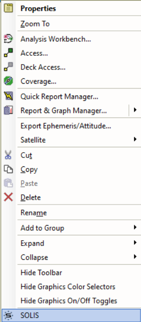
To access SOLIS, right-click the SatView satellite in the Object browser and select SOLIS at the bottom of the shortcut menu.
The SOLIS window will appear in the STK workspace.
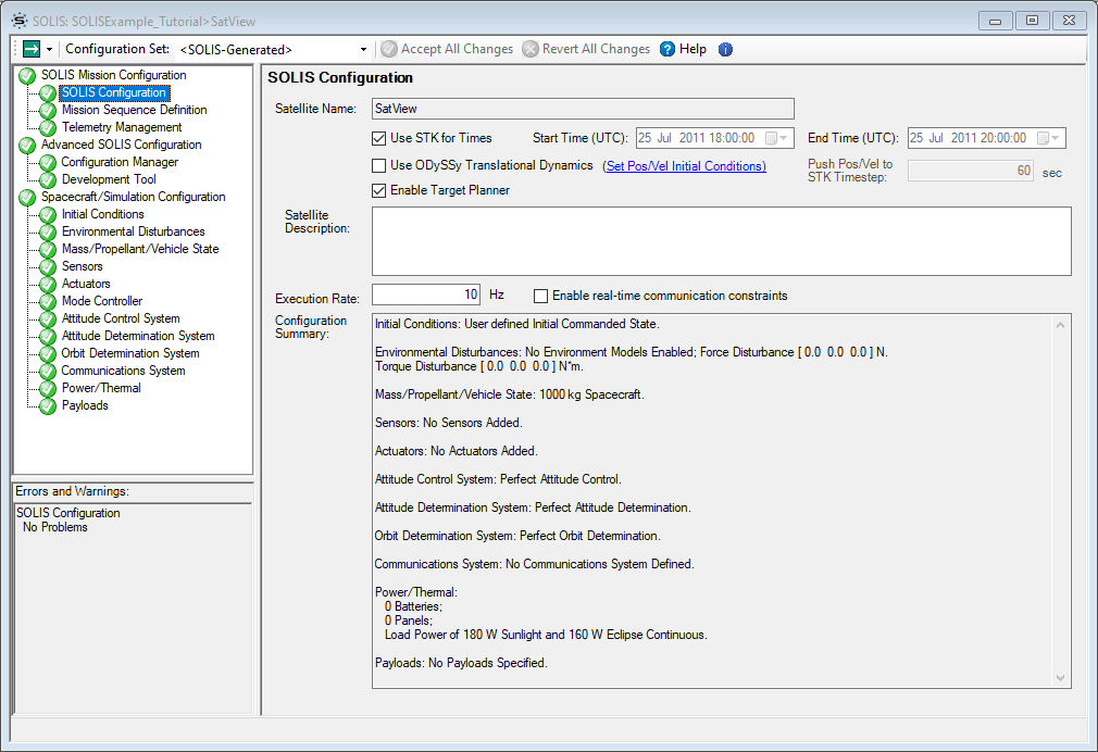
On startup, SOLIS displays the SOLIS Configuration page for the selected satellite. This page enables you to define the Simulation Execution Rate and view the entire Configuration Summary. The Configuration Summary automatically changes as you make changes to the Spacecraft/Simulation Configuration.
- In the Satellite Description field, enter:
"SatView is an imaging satellite and its mission in this scenario is to take pictures of cities in the Mountain West region."An asterisk (*) should now be displayed next to the SOLIS Configuration entry under SOLIS Mission Configuration, on the SOLIS page list. The asterisk indicates that the page has been modified. Changes made to one page may cause SOLIS to make changes to other pages, and those other pages will also marked with an asterisk. To lock-in your changes, you must click the
 button at the top of the SOLIS window.
 - Click to accept your changes now.
is not the same as saving. Use the STK File -> Save  to save UI input before closing/reloading the scenario.
Initial Spacecraft Configuration
Now that SOLIS is open, you can start to use it to configure the properties of the SatView satellite. The following steps will show you how to make some basic changes to the spacecraft's properties in SOLIS.
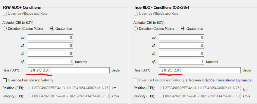
- On the Initial Conditions page, enter [2.0 2.0 2.0] deg/sec in BOTH of the "Rate (BDY)" fields. This will set the spacecraft into a spin at the beginning of the scenario.
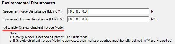
- On the Environmental Disturbances page, select Enable Gravity Gradient Torque Model. For this disturbance model to work properly we need to define an inertia matrix in Mass Properties.
- On the Mass Properties tab of the Mass/Propellant/Vehicle State page, enter:
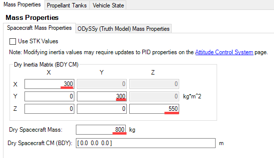
- Ixx: 300 kg*m^2 (top left corner)
- Iyy: 300 kg*m^2 (middle)
- Izz: 550 kg*m^2 (bottom right corner)
- Spacecraft Mass: 800 kg
- Now, go to the Modes tab on the Mode Controller page.
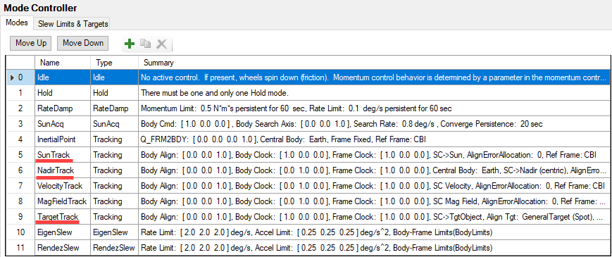
- Select SunTrack and enter the following vectors in the Mode Editor to correctly point the solar arrays in this mode:
- Alignment Vector (UBDY): [0 0 -1]
- Clocking Vector(UBDY): [0 1 0]
"Clocking" vectors are similar to "Constraint" vectors in STK. When in SunTrack mode, SatView will point at the Sun with the [0 0 -1] body vector while doing its best to align the [0 1 0] vector with the specified clocking vector. Alignment and Clocking vectors should not be identical/co-aligned in the body frame. Doing this will cause errors in the simulation because the spacecraft cannot align and clock with the same body vector. - Select NadirTrack in the Mode List and enter:
- Alignment Vector (UBDY): [0 0 1]
- Clocking Vector (UBDY): [1 0 0]
- Select TargetTrack and enter the following vectors:
- Alignment Vector (UBDY): [0 0 1]
- Clocking Vector(UBDY): [0 1 0]
- Go to the Power/Thermal page to define the satellite's power system. This spacecraft will have one battery and three solar panels.
- On the Power tab:
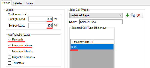
- Sunlight Load: 310 W
- Eclipse Load: 370 W
- Under "Add Variable Loads", select the Payloads and Communications check boxes.
- Click Add
 to add a "Solar Cell Type".
- Set the Solar Cell Type Efficiency to 0.15.
- On the Batteries tab, click Add to add a battery.
- On the Panels tab, click Add and make the following changes:
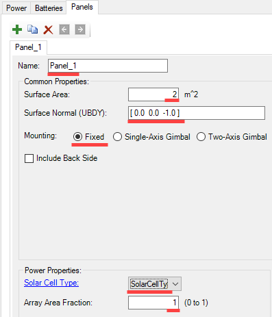
- Name: Panel
- Surface Area: 2 m^2
- Surface Normal (UBDY): [0 0 -1]
- Mounting: Fixed (no Gimbals)
- Select your newly created Solar Cell Type from the dropdown box under "Power Properties".
- Array Area Fraction: 1
- Click Copy
 twice and change the name of the copied solar panels to Panel 2 and Panel 3.
 - Click and then STK Save your changes.
Performing a Sun Pointing Command using Perfect Attitude Determination and Control
Follow these instruction to perform a simple sun-pointing command for the current configuration of the satellite.
Select Telemetry Data
SOLIS generates data that can be displayed with the STK Report & Graph Manager. However, one of the biggest drivers for SOLIS simulation run speed is the amount of telemetry being generated and stored. To minimize this issue, you must select the telemetry data that you want to have available to the Report & Graph Manager. This is done using the Telemetry Management Page page.
- Go to the Telemetry Management Page page under SOLIS Mission Configuration. Make the following selections on the Telemetry Interface tab:
- Make sure the Output Destination, at the top of this tab, is set to STK Data Provider (User Supplied Data).
- Highlight ODySSy Dynamics -> ODY EOM Summary by expanding the ODySSy Dynamics Group and click
 at the bottom of the telemetry list. The telemetry group will now be displayed in the Selected Telemetry table and the entry in the telemetry list will now be green.
 - Highlight ODySSy Power Thermal and click
 . This text in the telemetry list will change to boldface green because the entire packet group has been selected.
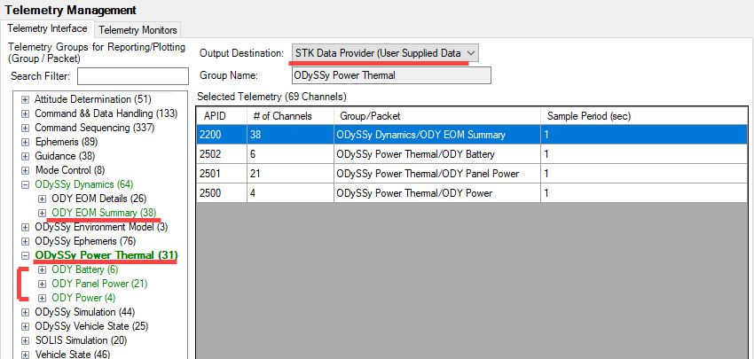
- Click and then STK Save your changes.
Define the Mission Sequence
- Go to the Mission Sequence Definition page and select the Sequence Editor tab:
- Click Add below the Sequence Library. When prompted to save the sequence file, save it as SunPointing.
- Create a Spacecraft Command for your new sequence by selecting Spacecraft Command from the pull down at the top of the page and then clicking Add .
- From the Command list, near the bottom of the page, expand Mode Control and then select Go To Rate Damp. This command will stop the slight initial spin our spacecraft is in, before pointing at the sun.
- Time from Sequence Start: 5 sec (This command will not kick off until 5 seconds after the Sequence Start.)
- Click Add at the top of the page, to add another Spacecraft Command.
- Expand Mode Control and then select Slew To Tracking. In the "Command Information" and "Time Editor" windows, set:
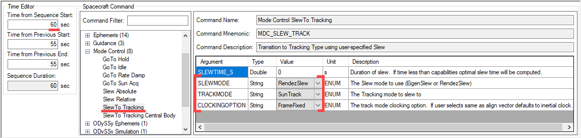
- SLEWMODE: RendezSlew (Use RendezSlew to get into tracking mode. This slew is defined on the Mode Controller page.)
- TRACKMODE: SunTrack (Set the tracking mode to be SunTrack. This is the same mode that was edited earlier from the Mode Controller Page.)
- CLOCKINGOPTION: FrameFixed (Set the clocking option to be FrameFixed. The spacecraft will clock to a fixed vector in a specified frame. Both the vector and the frame are defined on the Mode Controller Page.)
- Time from Sequence Start: 60 sec (This command will not kick off until 60 seconds after the Sequence Start.)
- Click Add
- Click Save
 under the Sequence Library to save your sequence.
 - Go to the Sequence Selection tab and add the SunPointing sequence to the Execution List by clicking SunPointing in the Sequence Library and then clicking
 .
. - Click and then STK Save your changes.
Run the Simulation
- If there are any changes not accepted (indicated by asterisks), click .
- Click the dropdown arrow next to the green button in the upper left of the SOLIS window and enable Start Paused.
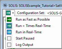
- Now go to the dropdown menu and select Run x Times Real-Time.
- Enter 5 as the multiplier and click .
- Arrange the windows so that you can view the Run status window and the "3D Graphics 1 - Earth" window.
- Click
 on the Run Status window when ready to start the simulation. (Be ready for the next step!)
 - Click
 when the run time is around 60 seconds. Notice that the spacecraft's orientation has not changed until 60 seconds into the simulation because there is a 60 second delay in the "SunPointing" sequence before the spacecraft will slew to SunTrack.
 - Click again. The Spacecraft Mode at the top of the SOLIS Run Status window will change to to RendezSlew. In the "3D Graphics 1 - Earth" window, watch as the spacecraft starts to slew to the sun.
- When the Run Time is around 180 seconds and the Spacecraft Mode has been SunTrack for a little while,
 the simulation.
 - Minimize the Run Status Window.
Create Analysis Graphs
- Right-click the Satview satellite in the STK Object browser and select Report & Graph Manager... from the shortcut menu.
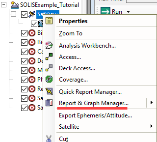
- Select the SOLISExample_Tutorial Styles folder and click the new graph
 button to create a new graph.
 - Name it AttRates and press Enter.
- When the Graph style properties open, enter User Supplied Data in the Filter field and click
 (or scroll down to it):
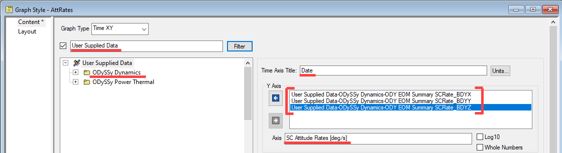
- Expand the User Supplied Data folder and then the ODySSy Dynamics folder.
- Add ODY_EOM_Summary SCRate_BDYX, ODY_EOM_Summary SCRate_BDYY and ODY_EOM_Summary SCRate_BDYZ to the Y axis of the plot by double-clicking the selection in the list or selecting it and then clicking the arrow pointing towards the Y Axis list of data.
- Enter Date as the Time Axis Title.
- Enter SC Attitude Rates [deg/s] as the Axis Title under Y Axis.
- Click .
- Create the Battery State of Charge graph:
- Create a New Graph Style again with , name it Battery State of Charge, and press Enter.
- When the Graph style properties open, enter User Supplied Data in the Filter field and click .
- Expand the User Supplied Data folder and the ODySSY Power Thermal folder.
- Add ODY Battery Current (A) to the Y Axis.
- Enter Date in the Time Axis Title.
- Enter Current [A] as the Axis Title for the Y Axis.
- Add ODY Battery SOC_pct to the Y2 Axis.
- Enter % SOC in the Axis Title for the Y2 Axis.
- Click .
- Create a New Graph Style again with
- Generate both of the graphs you just created.
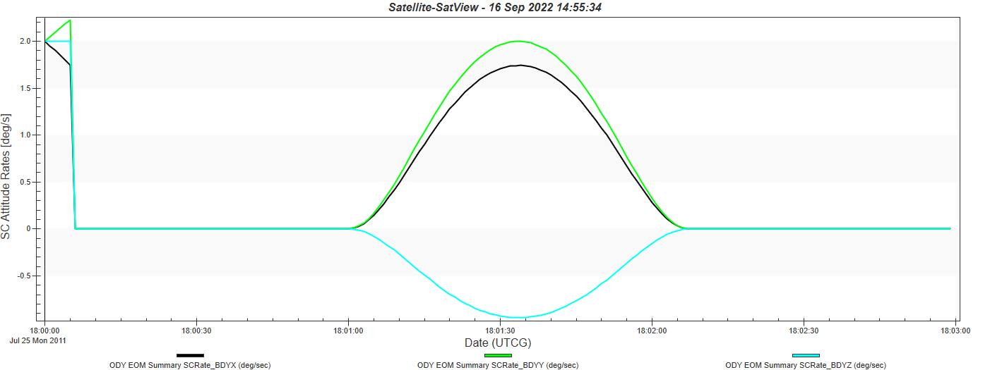
There are a couple of things to notice in the AttRates plot. The first is that the initial rate that we gave the spacecraft is near instantaneously brought to zero with the RateDamp command. The second is that the slew to SunTrack is smooth and the rate never overshoots or misses its targeted value. Both of these behaviors are because the spacecraft is using Perfect Control. This will not necessarily be the case when the ADCS systems are added.
For the Battery State of Charge graph, notice that your State of Charge (SOC) drops until the spacecraft points toward the sun, and then charge increases as the battery charges. Also notice that the Battery current moves from negative 11 A (pulling 11 amps) to a positive 15.2 A (charging 15.2 amps). When looking at both graphs together you can see the Battery current increases as the slew is happening in the AttRate plot. The current stays constant as the spacecraft holds its position.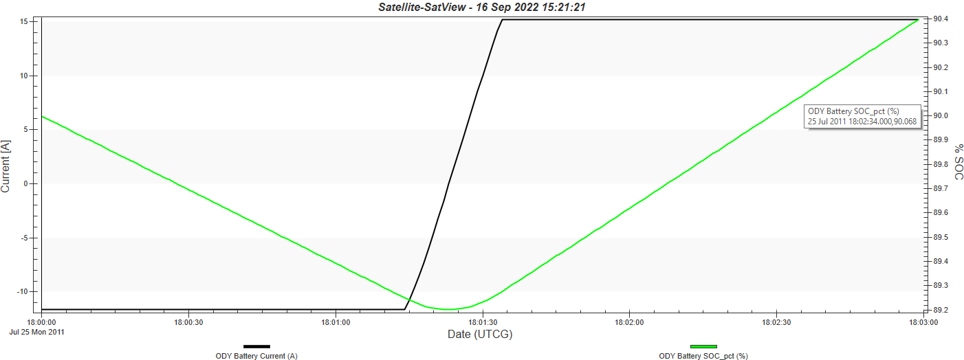
Next Steps: Subsystem Configuration
In the next part of this tutorial, you will configure some of the other major spacecraft subsystems.
Sensors and Attitude Determination
- Go to the Sensors page under Spacecraft/Simulation Configuration and click Run Wizard...
 .
. - View the various preference options available on the Sensor Wizard and make the following changes:
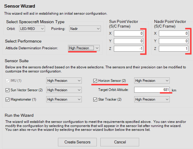
- Sun Point Vector (S/C Frame): [0 0 -1]
- Nadir Point Vector (S/C Frame): [0 0 1]
- Attitude Determination Precision: High Precision
- Enable Horizon Sensors
- Target Orbit Altitude: 681 km.
- Click
 . Feel free to take some time to review the sensors that have just been created and look at some of their customizable parameters.
 - While still on the Sensors page, click GPS Receivers in the sensors list and then click Add at the bottom of the list.
- Click the newly created GPS sensor and go to its ODySSy Simulation tab. Enter the following values:
- Position Bias In LVLH frame: [10 10 10] m
- Position Noise Standard Deviation In LVLH frame: [1 1 1] m
- Velocity Bias In LVLH frame: [0.1 0.1 0.1] m/s
- Velocity Noise Standard Deviation In LVLH frame: [0.001 0.001 0.001] m/s
- On the Orbit Determination System page, select PVT(Position, Velocity, Time) as the Ephemeris Source.
- Go to the Attitude Determination System page. Notice that Fixed Gain Filter is enabled; it was automatically changed from the default setting of Perfect AD. Verify the following values in the Attitude Sensor AD Configuration Table:
- Time Constant (sec):
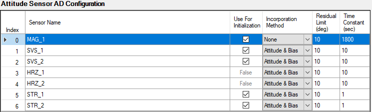
- Magnetometer (MAG_1): 1800
- Both Sun Vector Sensors (SVS_1/SVS_2): 10
- Horizon Sensor Pair (HRZ_1/HRZ_2): 10
- Both Star Trackers (STR_1/STR_2): 1
- Time Constant (sec):
- Click and then STK Save your changes.
Actuators and Attitude Control
- Go to the Actuators page. Click and verify the following default values:
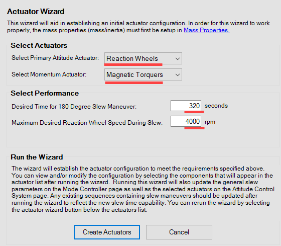
- Select a Primary Attitude Actuator: Reaction Wheels
- Select a Desaturation Actuator: Magnetic Torquers
- Desired Time for 180 degree slew maneuver: 320
- Maximum Desired Reaction Wheel Speed During Slew: 4000 rpm
- Click
 . A dialog box will appear that asks you about deleting existing sets; click **Yes**. Feel free to take some time to review the actuators that have just been created and look at some of their customizable parameters.
 - Click and then STK Save your changes.
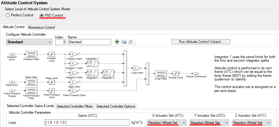
- On the Attitude Control System page under Spacecraft/Simulation Configuration on the main SOLIS window, make the following changes:
- Select PIID Control
- On the Attitude Control tab, use the dropdown menus for X/Y/Z Actuator Sets(ATC) and select Reaction Wheels Set for each one. This allows the reaction wheels to control each of the three spacecraft axes.
- Click
 .
.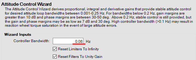
- Set the Controller Bandwidth to 0.08 Hz and click
 . A message will appear to warn you about overwriting values, press .
- Set the Controller Bandwidth to 0.08 Hz and click
- On the Momentum Control tab, set the Enabled State to Always Enabled and then select Magnetic Torquer Set for the X/Y/Z Actuator Sets.
- Go to the Mode Controller page to set up an Actuator Based Slew Limit. This will base the maximum speed of a slew off of the new actuator's capability and not any arbitrary rate limits.
- On the Slew Limits and Targets tab click on an existing Slew Definition and then click Add .
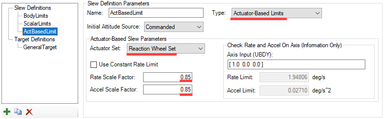
- Name this Slew Limit ActBasedLimit.
- Set the Type to Actuator-Based Limits.
- Make sure that Reaction Wheel Set is selected for the Actuator Set.
- Rate and Accel Scale Factors should both be set to 0.85 (85% of maximum actuator authority).
- Now, on the Modes tab, click on both the EigenSlew and RendezSlew modes and change the Slew Definition to ActBasedLimit selected as their Slew Definition.
- On the Slew Limits and Targets tab click on an existing Slew Definition and then click Add
- Click and then STK Save your changes.
Communications System and Payload
Because this is an imaging mission, and SatView has a camera payload on it, we need to model the communications system and payload. In STK, the satellite has a sensor but does not currently have a comms antenna. We will add that before making the associated changes in SOLIS.
Add a Sensor in STK (outside of SOLIS) which will be used to model the Communications System:
- Insert a default sensor attached to SatView from the STK Object browser.
- Name it SBandAnt and set the following parameters in its Property browser:
- Basic -> Definition
- Cone Half Angle: 12.5 deg
- Sensor Type - Simple Conic
- Basic -> Pointing
- Azimuth: 90 deg
- Elevation: 0 deg
- Basic -> Definition
- Apply changes and close the Property browser.
To set up the imaging and communications portion of the mission in the sequence definition, you will create a Kodak camera payload, and a transmitter and receiver for SOLIS to use. These objects are used to determine pointing directions, power usage, and data rates during its imaging mission.
- Back in SOLIS, go to the Communications System page, click Add at the bottom of the Communication System list, and name it S_BandTxRx.
- Make the following changes:
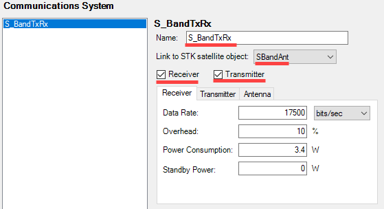
- Link to STK satellite object: SBandAnt
- Receiver and Transmitter: Enabled (default)
- Go to the Receiver tab and set or confirm the following property values:
- Data Rate: 17500 bits/sec
- Overhead: 10 %
- Power Consumption: 3.4 W
- Standby Power: 0 W
- Go to the Transmitter tab and set or confirm the following property values:
- Data Rate: 254000 bits/sec
- Overhead: 10 %
- Power Consumption: 76 W
- Standby Power: 0 W
- On the Antenna tab, clear the Omni-Directional check box and make the following changes:
- Boresight: [0.0 1.0 0.0]
- Field of View: 25 deg
- Click and then STK Save your changes.
Now, you will add the Payload:
- Go to the Payloads page, click Add at the bottom of the Payload List, and name it Kodak1000_Imager. Make the following change:
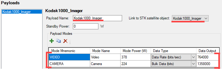
- Link to STK Satellite Object: Kodak1000_Imager
- Add the following Payload Modes to the Payload Modes table:
- Video Payload Mode
- Mode Mnemonic: VIDEO
- Mode Name: Video
- Mode Power (W): 378
- Data Type: Data Rate (bits/sec)
- Data Output: 764,000
- Camera Payload Mode
- Mode Mnemonic: CAMERA
- Mode Name: Camera
- Mode Power (W): 224
- Data Type: Bulk Data (bits)
- Data Output: 1,358,000
- Video Payload Mode
- Click and then STK Save your changes.
Putting It All Together: Define Sequences and Run the Imaging Mission
Set up Imaging and Communications Sequences
- On the Initial Conditions page set FSW Attitude Control Mode to NadirTrack and clear both Override Attitude and Rate check boxes.
- On the Mode Controller page, in the Modes tab, click RendezSlew and then click Add . This will create a new mode after RendezSlew. Make sure the new mode has the following settings:
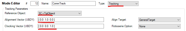
- Name: CommTrack
- Type: Tracking
- Reference Object: SC -> TgtObject
- Alignment Vector (UBDY): [0 1 0] (This mode will point the Communications system at the target, instead of the imager)
- Clock Vector (UBDY): [0 0 1]
- Click and then STK Save your changes.
- Go to the Mission Sequence Definition page and select the Sequence Editor tab.
- Add a sequence (bottom of the Sequence Library) and save it as KodakOpsOn.
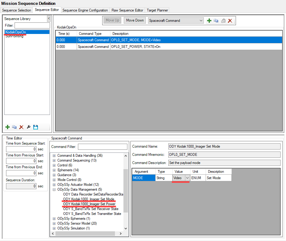
- Select Spacecraft Command from the pull down and click Add two times to add two Spacecraft Commands:
- ODySSy Data Management -> ODY Kodak1000_Imager Set Mode- Mode Value: Video
- ODySSy Data Management -> ODY Kodak1000_Imager Set Power- Power State Value: On
- Click the Save button to save the sequence you just created.
- Add another sequence called KodakOpsOff.
- Add the following Spacecraft Command to the new sequence:
- ODySSy Data Management -> ODY Kodak1000_Imager Set Power- Power State Value: Off
- Add
- Save the sequence you just created.
- Add another sequence called SBandOn.
- Add the following Spacecraft Commands to the new sequence:
- ODySSy Data Management -> ODY S-BandTxRx Set Receiver State- Power State Value: On
- ODySSy Data Management -> ODY S-BandTxRx Set Transmitter State- Power State Value: On
- Add
- Save the sequence you just created.
- Add another sequence called SBandOff.
- Add the following Spacecraft Command to the new sequence:
- ODySSy Data Management -> ODY S-BandTxRx Set Transmitter State- Power State Value: Off
- Add
- Save the sequence you just created.
- Click and STK Save your changes.
Configuring the Target Planner
- In the Mission Sequence Definition page, select the Target Planner tab.
- Un-check the Use SOLIS Times box and change the end time to 25 Jul 2011 18:40:00.
- Set the Attitude Between Targets to the following parameters. This will cause the spacecraft to charge its batteries when it is not pointing at a target:
- Slew: RendezSlew
- Destination: Sun Track (Alignment Mode)
- Clocking: Frame Fixed
- Minimum Dwell: 500 sec
- Make sure the list of targets is in the same order as the Object browser on the left. If not, set the "Action" to Load STK Target Objects and click
 .
. - In the Targeting Configurations window, click Add to create a new targeting configuration.
- Define the following parameters:
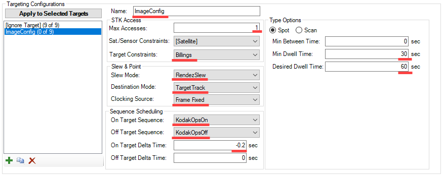
- Name: ImageConfig
- Max Accesses: 1 (this is the maximum number of times you want it to visit this particular target)
- Target Constraints: Billings (This target was created with a 10 deg minimum elevation mask. By selecting this option, all targets using this config will have the same minimum elevation constraint)
- Slew Mode: RendezSlew (Use RendezSlew to point at the target)
- Destination Mode: TargetTrack
- Clocking Source: Frame Fixed
- On Target Sequence: KodakOpsOn
- Off Target Sequence: KodakOpsOff
- On Target Delta Time: -0.2 (Begin executing the sequence 200ms prior to arriving at the target)
- Off Target Delta Time: 0
- Minimum Dwell: 30 (this is your minimum amount of time it will spend on a target)
- Desired Dwell: 60 (this is your ideal amount of time it will spend on a target)
- Select the nine STK targets in the target list and click
 to apply the ImageConfig to each of them.
 - Click and then STK Save your changes.
Running the Target Planner
- Go to the Sequence Selection tab and make sure that the Execution List is empty by removing the SunPointing sequence (select "SunPointing" and click
 ).
). - Click and then STK Save before running the Target Planner.
- Go back to the Target Planner tab and set the "Action" to Generate Sequence and hit .
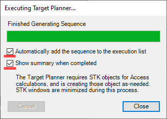
- Name this generated sequence ImagingSequence and click save. This will disable your User Interface while the Target Planner runs.
- When the Target Planner has finished performing all of the calculations, verify that both checkboxes are selected and press Close.
Target Planner Results
- After closing the target planner execution window, the Results Summary will open.
- Look at the "Accesses Scheduled" column. A value of 1 indicates that there is one access schedule for the target; the value of 0 indicates that there is no access scheduled.
- Look at the "First Schedule Time" column. It provides the time of the scheduled access, or N/A for a target without access.
- You can save this as a
.csvfile for future reference, or close it. For now, just click to close it. - The Target Planner has generated a sequence, which can be viewed in the Sequence Editor. Go to the Sequence Editor tab and click the ImagingSequence sequence. The first Sequence Element is a Comment that provides the details of the sequence plan.
- Click and then STK Save your changes.
- Click on the Sequence Selection tab and verify that ImagingSequence is the only sequence in the Execution List and that the Mission Elapsed Time (sec) is 0.0.
- Now, Run the scenario at 20 x Real-Time speed, and watch as the spacecraft dwells on as many targets as it can.
- After the run is complete (past 1200 seconds) feel free to open the AttRate and Battery State of Charge plots to see what they look like for the more complicated scenario.
Changing Priority
Since there were targets that were not imaged, you can increase their chances of being imaged by increasing their priority.
- On the Target Planner tab, select the following targets:
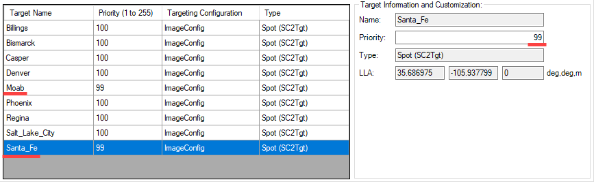
- Moab
- Santa Fe
- Enter 99 in the Priority field for each target.
- On the Sequence Selection tab, the ImagingSequence sequence from the Execution List
- Go back to the Target Planner tab and set the "Action" to Generate Sequence and click to run the Target Planner again. Save this Sequence as ImagingSequence_Priority.
- Look at the summary and notice that the two targets that were missed last time made it into the list this time, at the cost of preventing others from being imaged. In order to image all of the locations in one pass, you would have to make changes to the actuators or slew limits to increase the agility of the spacecraft or reduce the dwell time of each target opportunity.
- Run the scenario with ImagingSequence_Priority as the only sequence in the Execution List and watch as SatView images the targets.
Adding Communication Pointing
- On the Target Planner tab, click Add to create another Targeting Configuration and give it the following parameters:
- Name: CommConfig
- Max Accesses: 1
- Target Constraints: Billings
- Slew Mode: RendezSlew
- Destination Mode: Comm Track
- Clocking Source: Frame Fixed
- On Target Sequence: SBandOn
- Off Target Sequence: SBandOff
- On Target Delta Time: -0.2 (Begin executing the sequence 200ms prior to arriving at the target)
- Off Target Delta Time: 0
- Minimum Dwell: 30
- Desired Dwell: 60
- Select "Phoenix" from the target list and press the button to set that configuration.
- Set the priority for Phoenix to 99 so that the satellite will not miss its downlink. (Reset Moab and Santa Fe back to 100.)
- Set the "Action" to Generate Sequence and click and call it CommSequence. Now it will generate a whole sequence for the scenario where data will be collected and transmitted back down to the ground.
- ImagingSequence_Priority from the Execution List on the Sequence Selection tab.
- Click and then STK Save your changes.
- Run the scenario at 20x Real-Time speed and watch SatView image the targets and then transfer data down to the ground at the Phoenix target.
More SOLIS
This tutorial has gone over a few of the different capabilities of SOLIS, but SOLIS has much more to offer. Learn more about SOLIS in the rest of the portal here. Additionally, examples of various features are on the Example Scenarios page.